|
| This is the inverting op amp circuit. By changing the voltage in and measure the effects of the op amp. so that the saturation can be seen as well as the voltage that seeps in from the source when the voltage input is zero. |
 |
| This is the break down of the Op Amp as though it where two seperate components that are just proportionally reliant on each other. The voltage across the resistor and the voltage from the source. Gosh there is so much stuff going on here, It hurts to look at the day before the celebration. |
 |
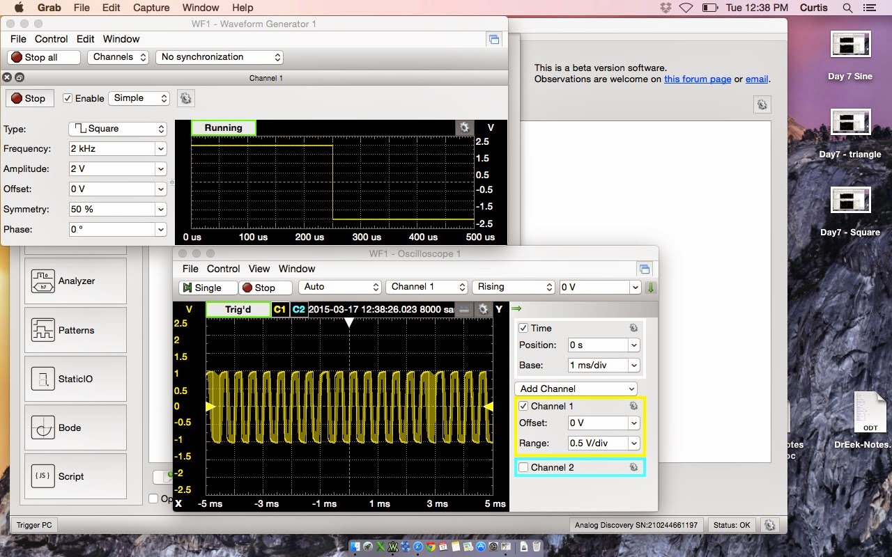
| This is the circuit itself using the Op Amp. You can see the source supplied and and the oscilloscope measuring the resistance. I hope there are not any questions about how to use waveform, I would be in trouble. Time to sleep so I have energy to Celebrate tomorrow.!!!!! CELEBRATE GOOD TIMES COME ON!!!! |