 |
| This circuit uses a capacitor with an inverting op amp. |
 |
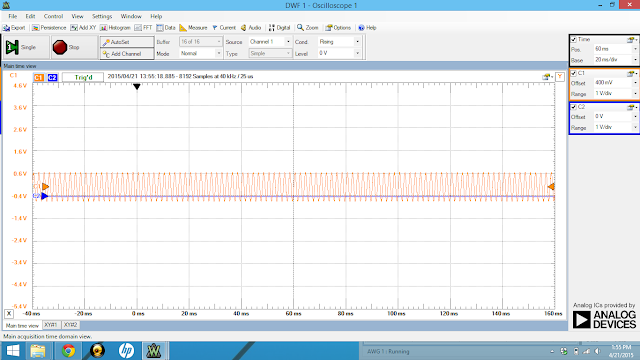
| This is the graph of the output voltage at 1kHz frequency. You can see that the max is approximately 1.22 V. There is a small amount of excess noise, but the voltage is very consistent. |
 |
| When the frequency is 2kHz, there appears to be a lot more noise. This has to do with the increase in amplitude and in increase in frequency. |
 |
| This a very neat graph at 500Hz. It looks very boring and simple and it has a small amount of voltage. |

No comments:
Post a Comment