Thursday, June 11, 2015

6-2-15

A practice problem. Calculating the equation for HdB. The numerator recognizes the zeroes and any offset. The denominator is the poles. remember that 

This is an example for bode plots. Looking at the relationship between Decibels and power ratios. 

5-26-15

This is a practice example problem. This is the predicted outcome of the circuit. Graphing current though time and the voltage through time. Then after creating the equation and implementing the measured values.

This is the circuit that the previous example is using the see if you can predict the voltage and current.

This is finding the power through a load. and then alternating the resistance outside of the load to see how the effects on the power. This is calculating the apparent power, the average power and the power factor.

This is the picture of the circuit being tested. Everything is in series. This is an extremely simple circuit. 


This is the circuit using a large resistor. As the drop across the large resistor is greater the power through the load is less. This is essentially, also what happens throughout the rest of the lab. The final two pictures depict the expect change in voltage through the load.


The resistor is really only measured to calculate the current. 


The energy is the highest in this graph. 

5-14-15

This is the voltage through an AC current at 1kHz.

Same circuit  5kHz.

Same circuit 500Hz.

This is the circuit that everything is being measured and the power source is being applied to. This is meant to be able to measure the impedance of the circuit so that a potentiometer can be used to apply a similar amount of impedance and the power can be maximized through the pot.

This chart shows the phase shifts between the voltage and the current. 

In this circuit the potentiometer is parallel in order to maximize the power across the potentiometer. 

This is the output of the circuit. Measuring the voltage as it fluctuates through the pot.

5-12-15

This is measurements of voltage through an AC circuit. You can see that the voltage measurements are out of phase. The red line is the mathematical interpretation of the current through a resistor. The voltage is running through an inductor. So the voltage is leading the current.

This example uses nodal analysis to calculate the voltage in the circuit. The voltage is being supplied as a cosine wave. As the voltage travels through the inductors and the capacitor, it becomes out of phase with the current. 

This example uses mesh analysis to calculate the phase shift between the voltage and the current. It is important to recognize that instead of measuring resistance, the impedance is always what is measured.

In the lab exercise, different components were attached to an AC power supply. This way the shift in the phase between the current and the voltage could be seen and its relationship to the circuit element could be established.

This is the theoretical calculations, and what is expected to happen through the circuit.

This is the experimental voltage and current graph, through the oscilloscope. 

Thursday, May 21, 2015

5-7-15

This is looking impedance of different circuits. Using the equation for impedance in an inductor to be j imaginary * natural frequency * inductance. The impedance of a capacitor is the inverse of j imaginary * natural frequency * capacitance. 

This is all three of the circuits built on one bread board, so that each circuit could be looked at one after another with ease. This is to calculate the voltage of the circuit

This graph is through the inductor. It shows how the inductor is fighting the change in the voltage. It oscillates about 0V while the voltage through the resistor oscillates through what looks like a DC offset because of the voltage that the inductor is fighting. This has a frequency of 500 Hz.

This is the same circuit only in this case the frequency is 1K Hz.

This is the current through the resistor verses the voltage from the capacitor. So the current is decreasing the voltage is being being released from the capacitor. This allows this seeming mirror image. This beautiful graph. Like artwork.

Sunday, May 17, 2015

4-30-15

This is the circuit with a capacitor in parallel with a resistor and an inductor. It is measuring the voltage only through those parallel components. This lab is a question on my second celebration. I got a number of things wrong on this lab as well as getting things wrong on the celebration.

This is a good example of why I should have my labs done on time.

This says that the circuit is overdamped.  The graph of the voltage says other wise. Implying that there is some miscalculation in the neper frequency and the natural frequency. The correct equation should have been e^at(Acost(wt) + Asin(wt)). Then solve for A and B using initial value amounts.

This circuit is underdamped. Even though on the previous screen we say that it is over damped. 

4-28-15 : AC RLC circuit

This is a basic RLC circuit, using a waveform generator to produce a sinusoidal wave function for an AC voltage source. This is a second-order circuit. in this case alpha is less than omega so we expect an underdamped case.

This is the prelab. Though it does not include the equations for s1 and s2. The equation for underdamped i(t) = e^(-at)(B1coswt+b2sinwt) 

This graph shows the underdamped response.

4-21-15

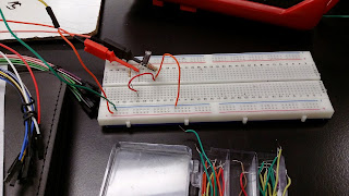
This circuit uses a capacitor with an inverting op amp.

This is the schematic for the op amp and the inverting amplifier. The theoretical output voltage was 2 pi multiplied by the frequency, the resistance, the capacitance, and the amplitude. It then oscillates in a sinusoidal wave. 

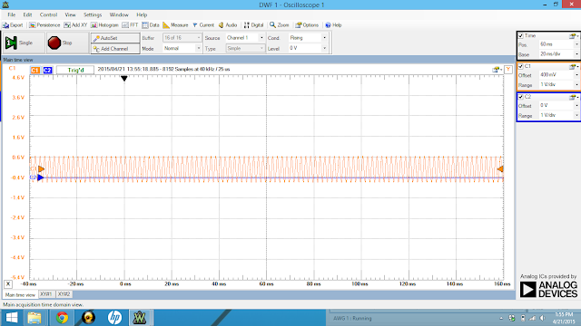
This is the graph of the output voltage at 1kHz frequency. You can see that the max is approximately 1.22 V. There is a small amount of excess noise, but the voltage is very consistent.

When the frequency is 2kHz, there appears to be a lot more noise. This has to do with the increase in amplitude and in increase in frequency.

This a very neat graph at 500Hz. It looks very boring and simple and it has a small amount of voltage.

4-16-15